Nutr track roller
Track rollers - NUTR track roller
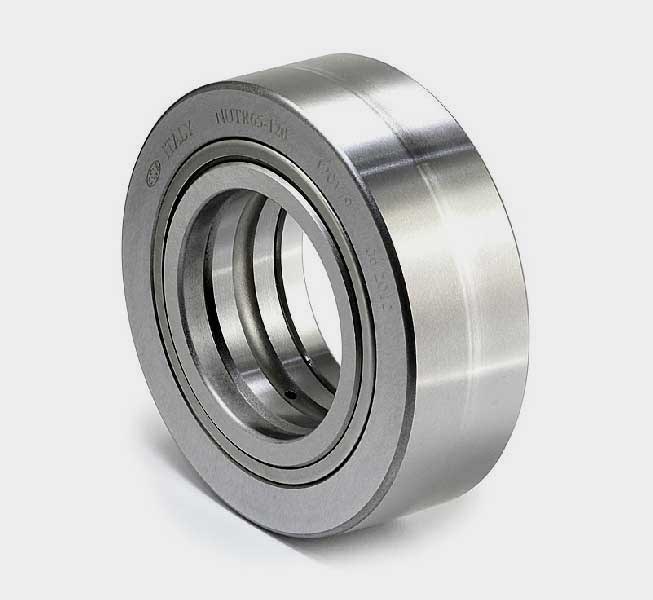
Technical Drawing and Exploded View - NUTR track roller


1. Seal sheet
2. Support thrust ring
3. Outer ring
4. Cylindrical rollers
5. Inner ring
6. Support thrust ring
7. Seal sheet
2. Support thrust ring
3. Outer ring
4. Cylindrical rollers
5. Inner ring
6. Support thrust ring
7. Seal sheet
Technical Data - NUTR track roller
| C.R. rif / ref | d (mm) | D (mm) | B (mm) | C (mm) | d1 (mm) | r min. (mm) | r1 min. (mm) | Cw (kN) | Cow (kN) | Vel Max Speed (RPM min-1) |
|---|---|---|---|---|---|---|---|---|---|---|
| NUTR 15 | 15 | 35 | 19 | 18 | 20 | 0,6 | 0,3 | 15 | 16,8 | 6500 |
| NUTR 17 | 17 | 40 | 21 | 20 | 22 | 1 | 0,5 | 18,4 | 22,6 | 5500 |
| NUTR 15 42 | 15 | 42 | 19 | 18 | 20 | 0,6 | 0,3 | 18,1 | 21,9 | 6500 |
| NUTR 17 47 | 17 | 47 | 21 | 20 | 22 | 1 | 0,5 | 21,3 | 28 | 5500 |
| NUTR 20 | 20 | 47 | 25 | 24 | 27 | 1 | 0,5 | 28 | 35 | 4200 |
| NUTR 20 52 | 20 | 52 | 25 | 24 | 27 | 1 | 0,5 | 31,5 | 41 | 4200 |
| NUTR 25 | 25 | 52 | 25 | 24 | 31 | 1 | 0,5 | 29 | 37,5 | 3400 |
| NUTR 25 62 | 25 | 62 | 25 | 24 | 31 | 1 | 0,5 | 35,5 | 50 | 3400 |
| NUTR 30 | 30 | 62 | 29 | 28 | 38 | 1 | 0,5 | 40 | 50 | 2600 |
| NUTR 30 72 | 30 | 72 | 29 | 28 | 38 | 1 | 0,5 | 47,5 | 64 | 2600 |
| NUTR 35 | 35 | 72 | 29 | 28 | 44 | 1,1 | 0,6 | 44,5 | 60 | 2100 |
| NUTR 35 80 | 35 | 80 | 29 | 28 | 44 | 1,1 | 0,6 | 51 | 72 | 2100 |
| NUTR 40 | 40 | 80 | 32 | 30 | 51 | 1,1 | 0,6 | 55 | 75 | 1600 |
| NUTR 45 | 45 | 85 | 32 | 30 | 55 | 1,1 | 0,6 | 56 | 78 | 1400 |
| NUTR 40 90 | 40 | 90 | 32 | 30 | 51 | 1,1 | 0,6 | 66 | 95 | 1600 |
| NUTR 50 | 50 | 90 | 32 | 30 | 60 | 1,1 | 0,6 | 57 | 81 | 1300 |
| NUTR 45 100 | 45 | 100 | 32 | 30 | 55 | 1,1 | 0,6 | 71 | 107 | 1400 |
| NUTR 50 110 | 50 | 110 | 32 | 30 | 60 | 1,1 | 0,6 | 76 | 120 | 1300 |
Cw: Dynamic load - Cow: Static load
Technical Characteristics - NUTR track roller
The main characteristic of this series of rollers is the high thickness of the outer ring, which is suitable to bear high specific pressures and the thrusts deriving form the use of these bearings as pressure rollers, cam followers, conveyor belt rollers, bearings for fork lift masts.
Other important features of these bearings are:
- Outer ring with double border of the rollers obtained entirely and accurately grinded to allow the roller to bear loads with axial components. The ring is usually cambered on the outer part, in order to improve working condition with heavy loads and to prevent the concentration of load onto side bands of the raceway. On request, C.R. can supply rollers with cylindrical outer surface.
- Inner ring with holes and channels for the inflow of lubricants.
- Grinded thrust rings, which form a labyrinth protection system, along with steel sealing sheets forced on the outer ring. One of the lateral thrust rings can be a closed thrust ring, to allow the fixing of the rollers at the edge of the shaft.
- Full-complement of grinded flat head rollers.
- Tolerance of execution according to normal class, possibility of special execution according to class P5 (DIN 620).