
Technical Drawing
Exploded View

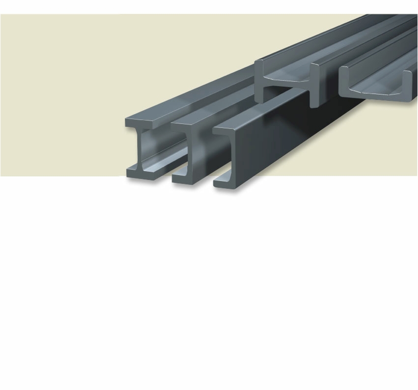
“U” standard lift guides are used in different industrial fields: fork lift masts, food industry, car industry, ceramic industry, machine tool industry.
Normally small and medium size combined bearings are used inside these guides.
They are manufactured in ST 52.3 steel.

Lift Guides


C.R. Ref.
3018
3019
3275
3020
2912
3100
3353
b1
14
18
20,5
20,5
18,96
22
25,6
(b)
98
113,9
129,6
129,6
140,2
152,4
175
b2
70
77,9
88,6
88,6
102,28
108,4
123,8
Tol.
±0,5
±0,5
±0,5
±0,5
±0,8
±0,5
±0,5
h
65
66
72
81
69,9
83
90
Tol.
+1
+1
+1
+1
-
±0,5
±0,5
Tol.
±1
±1
±1,25
±1,25
+1,60
±1
±1,3
s
9
11
12
12
12,7
14
15
Tol.
±0,5
±0,5
±0,5
±0,5
±0,5
±0,5
±0,5
c
15
15
15
15
*
20
20
R2
10°
10°
10°
10°
*
12°
5°
d
3
3
3
3
*
3
5
Tol.
±1
±1
±1,25
±1,25
+1,60
±1
±1,3
Weight
Kg/m
19,4
25,3
31,2
34,1
31,2
40,8
51,4
Wx
Cm3
70
102
143
160
157
219
322
R1
91°+1°
91°+1°
91°+1°
91°+1°
*
91°+1°
91°+1°
“I” STANDARD
Dimensions

“U” PRECISION
C.R. Ref.
EC 065 L
EC 074 L
EC 082 L
EC 093 L
EC 112 L
EC 128 L
EC 154 L
H
86,5
103
121
135,5
157
175
201
C
65
74
82
93
112
128
154
Jx Cm4
125,1
248,9
439,1
792
1357,5
1891,5
3098,7
B
35
39
39,2
51
59
64
69
Wx
Cm3
28,9
48,3
73,4
116,9
172,9
227,6
308,3
Jy Cm4
12,9
23,2
30,3
75
126,8
174,2
230,8
Wy
Cm3
10,7
16,3
21,4
39,6
59,1
77,4
46
Weight
Kg/m
9,44
13,14
17,87
25,16
31,47
37,71
45,98
Ex
mm
12,09
14,22
14,44
18,94
21,46
22
22,8
Ey
mm
43,25
51,5
60,5
67,75
78,5
87
100,51
Dimensioni
Moments of Inertia
Modulus of Resistance
Dimensions

“U” STANDARD
C.R. Ref.
EC 053
2890
2867
2810
2811
2862
2891
2757
b1
6
12
16,2
21,3
23
24,4
25,6
25,7
(b)
65
86,5
103,2
121,3
135,4
157,2
175
201,5
b2
53
62,5
70,8
78,7
89,4
108,4
123,8
150,1
Tol.
±0,5
±0,5
±0,5
±0,5
±0,5
±0,5
±0,5
±0,5
h
30
36
40
41
53
61,2
66,2
71,2
Tol.
±0,4
+1
±0,5
±0,5
±0,5
±0,5
±0,5
±0,5
Tol.
±0,5
±0,8
±0,8
±0,8
±0,8
±0,8
±0,8
±0,8
h1
6
7
7,7
10,8
12,7
14
16,2
19,4
Tol.
±0,5
±0,5
±0,5
±0,5
±0,5
±0,5
±0,5
±0,5
c
4
15
15
15
15
15
15
20
r2
4
2-
2-
2-
2-
2-
2-
2-
d
4
3
3
5
5
5
5
5
r3
*
4
5
5
5
5
5
6
Weight
Kg/m
5,3
10,5
14,8
20,9
28,6
35,9
42,9
52,3
Wx
Cm3
11,9
32
53
81
128
190
250
340
r1
6
≤ 6
≤ 6
≤ 6
≤ 6
≤ 6
≤ 6
≤ 8
Dimensions


C.R. Ref.
FI 123
FI 149
FM 165
FM 190
FM 220
FM 250
FM 280
FM 280 R
mm
800
800
600
600
1.200
1.200
1.200
1.200
KN
60
80
100
160
180
280
360
420
H
176
205
230
255
295
345
375
395
C
123,3
149,3
165,4
190,4
220,4
250,4
280,4
280,4
S
15
16
16
20
20
25
30
30
B
90
110
95
130
150
160
190
190
D
*
*
80
80
125
125
125
125
Jx Cm4
2960
5320
6825
11983
21035
37883
55210
69230
Jy Cm4
325
615
475
1203
2123
3279
5498
6642
Wx
Cm3
336
519
593
940
1426
2196
2945
3505
Dimensions
Moment of Inertia
Modulus of Resistance
Wy
Cm3
72
112
100
185
283
410
578
700
Weight
Kg/m
52,8
68,7
71
100
128
175
215
245
“I” WELDED


C.R. Rif.
FC 123 L
FC 149 L
FC 165
FC 190
FC 220
FC 250
mm
600
600
600
600
600
600
KN
50
60
80
100
160
200
H
175
202
230
255
295
344
C
123,3
149,4
165,4
190,4
220,4
250,4
S
16
19,4
18
22
20
26,5
B
66
71,2
57,5
77
85
94
D
*
*
80
80
125
125
Jx Cm4
2181,6
3480,6
4410,5
7631,6
12632,7
23371,6
Jy Cm4
206
276,5
174,6
434,2
6720,4
1117,4
Wx Cm3
249,3
344,6
383,5
598,6
856,5
1358,8
Dimensions
Moments of Inertia
Modulus of Resistance
Wy Cm3
86,7
114
87,5
167,7
231,7
344,9
Weight
Kg/m
42,37
52,31
53,3
73,7
86,1
122,8
Nom. cap.
Centre of Grav.
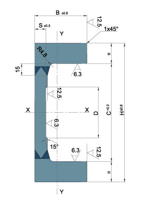
“U” WELDED
Material: UNI Fe 510 C – DIN St 52.3
The profiles can be cut on request of the customer, maximum length is 12 m.
Material: UNI Fe 510 C – DIN St 52.3
The profiles can be cut on request of the customer, maximum length is 12 m.
Material: UNI Fe 510 C – DIN St 52.3
The profiles can be cut on request of the customer, maximum length is 10 m.
Material: UNI Fe 510 C – DIN St 52.3
The profiles can be cut on request of the customer, maximum length is 10 m.
Material: UNI Fe 510 C – DIN St 52.3
The profiles can be cut on request of the customer, maximum length is 10 m.
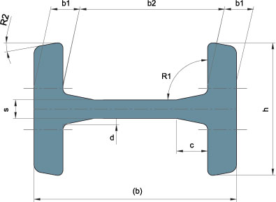
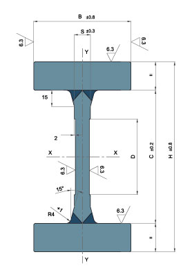
Standard “I” profiles are exclusively used to build the fork lift masts.
The “I” profile has been realized in order to satisfy the needs of the manufacturers of fork lifts.
The combined bearings are used inside these profiles, like in the case of the “U” profiles.
They are manufactured in ST 52.3 steel.
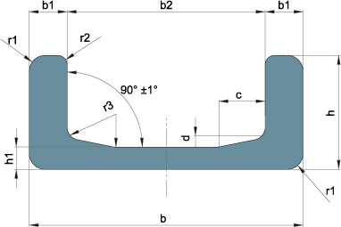
“U” precision lift guides are obtained from “U” standard lift guides.
They are processed by a machine tool in order to have a high level of processing with extremely limited tolerances.
Used with “DR” special combined bearings inside, they represent a very good alternative to the linear guide system.
They are made of ST 52.3 steel.
“U“ PRECISION
“I“ STANDARD
“U“ STANDARD
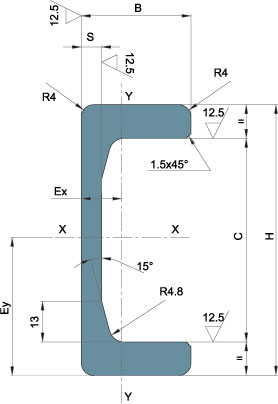
The “U” welded lift guides are obtained from the assembling of welded laminated plates.
They are used in heavy industry, in high load fork lift masts, in big size handling plants.
They are made of ST 52.3 steel.
“U“ WELDED
The “I” welded lift guides are obtained from the welding of laminated plates.
They are used in the same application fields as the “U” welded lift guides.
Jumbo series combined bearings are used inside these guides.
“I“ WELDED
Centre of Grav.
Nom. cap.

C.R. s.r.l. -
